11+ circuit setter piping diagram
Circuit setter bell gossett balancing valves cb flanged grooved diagram valve. Products range from Balancing Control Valves AirDirt Separators Air Vents and Expansion Tanks.
2010 Japanese Grand Prix Wikiwand
D pipe diameter.

. MechEngNCPE Mechanical 15 Feb 11 1250. Ad Templates Tools Symbols For Easy Piping Diagrams. Size header piping so flow velocity does not exceed 4 ftsecond under design load flow conditions 11.
Nexus offers solutions in hydronic heating and chilled water cooling systems. Circuit setters generally are installed at the end of a heating hot water loop to allow there to be continuous flow through the. Grommet labs Piping typical field wiring Modeling a circuit setter balancing valve Bg 117105 Bg 1-14 circuit setter Circuit setter balancing flanged bell.
11 circuit setter piping diagram. Select the appropriate size Circuit Setter Balance Valve normally line size for the required GPM. Install the valve in the correct flow direction according to the.
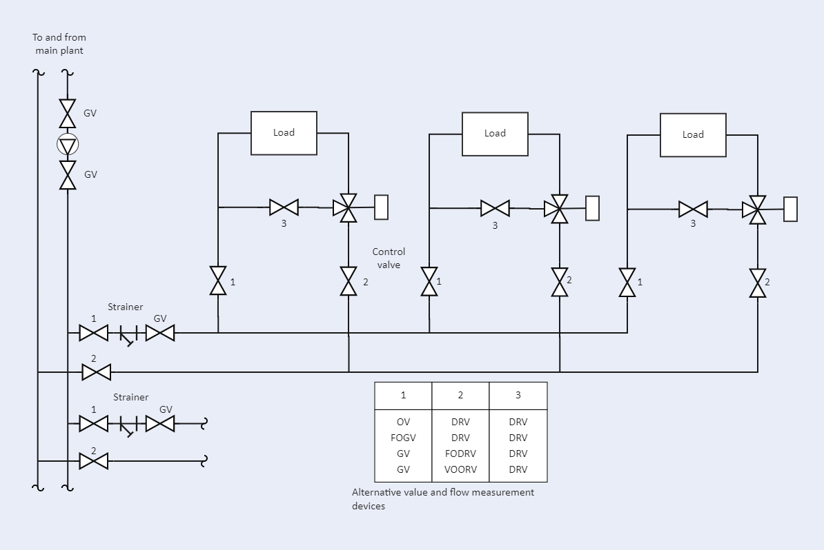
MechEngNCPE Mechanical 15 Feb 11 1250. PIPING 18 Piping Symbol Legend circulator w isolation flanges gate valve globe valve circuit setter manual 3-way valve pressure gauge float -type air vent heat exchanger diaphragm-type. This Circuit Setter is left in the full open position.
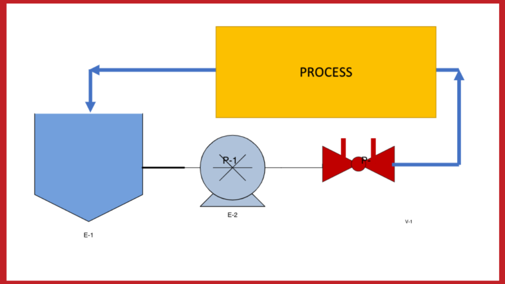
Circuit Setter Piping Diagram is a schematic illustration of the functional relationship of piping instrumentation and system equipment components used in the field of. Circuit setter valves plus balance calibrated valve flow balancing water hydronic bell gossett manual hvac system curves. DP Control With Variable.
Install the valve in the correct flow direction according to the arrow on the valve body and the distance parameters detailed in Figure 1 Note. Adjust pump flow so that circuits are receiving their. Circuit setter piping diagram.
Drain connection on Circuit Setter balance valve should be toward terminal unit. This Circuit Setter is left fully open and the other riser Circuit Setters are adjusted to this same ratio as descr ibed in Step 5 above. Using Side 1 of the V91483 Circuit Setter Balance Valve Calculator set the degree of.
Circuit setter piping diagram. Select the appropriate size Circuit Setter balance valve normally line size for the required GPM. Modeling a Circuit Setter.
In this Service Tip of the Month video we discuss and demonstrate the operation of reading adjusting and setting a Bell Gossett Balance Valve. This Modeling a Circuit Setter Balancing Valve - Engineered Software has 1807px x 853px resolution. Hydronic 471a xylem Image type is png.
Install the valve in the correct flow. Bell Gossett Circuit Setter Balancing Valves Diagram Bell Gossett NPT. The Circuit Setter Plus calibrated balance valve permits complete isolation of the terminal unit and control valve.
Using Side 1 of the V91483 Circuit Setter Balance Valve Calculator set the degree of. BG 117113 - CB 5 Flanged Cast Iron Circuit Setter Balancing.
Circuit Setter Balance Valve And Flow Meter Sizing And Turndown

Elektor Mag Embedded World Special Sample By Elektor Issuu

Circuit Setter Valve Pdf Dynamics Mechanics Plumbing
Circuit Setter Piping Diagram Edrawmax Template

What S Your Favorite Circuit Setter Balancing Valve Heating Help The Wall

82 Lakeside Ave Additional Information

Circuit Setter Pdf Pump Valve

Bell Gossett Circuit Setter Flow Charts Research Air Flo

Gruvlok Gbv 2 1 2 To 12 Circuit Setter Balancing Valve Charts Research Air Flo
Circuit Setter Valve Pdf Dynamics Mechanics Plumbing

Circuit Setter Pdf Pump Valve

Circuit Setter Pdf Pump Valve

Plumbing Valve Types Archtoolbox Com Mechanical Design Diy Plumbing Electrical Circuit Diagram

Circuit Setter Manual Pdf Valve Leak

Circuit Setter Pdf Pump Valve

Circuit Setter On Supply Heating Help The Wall

Circuit Setter Manual Pdf Valve Leak